Dual Compressor Wiring Diagram

Vt Commodore Ignition Wiring Diagram, Complete Wiring Diagrams For Holden Commodore VT, VX, VY, VZ, VE, VF, 5.36 MB, 03:54, 32,796, John Amahle, 2018-08-01T19:37:41.000000Z, 19, Vt Commodore Ignition Wiring Diagram, to-ja-to-ty-to-my-to-nasz-swiat.blogspot.com, 1272 x 1800, jpeg, bcm pcm 12j swiat nasz, 20, vt-commodore-ignition-wiring-diagram, Anime Arts
Contactor volts input getting air conditioning doityourself upvote. 115/230 volt motor wiring diagram. Only getting 18 volts at contactor input dual compressor wiring diagram. I have a electric fan in a 1965 mustang 289 v8.
8 images about i have a electric fan in a 1965 mustang 289 v8. Viair recommends that you reference the plumbing diagrams below when installing your compressor. Set by the gdpr cookie consent plugin, this cookie is used to record the user consent for the cookies in the advertisement category. This cookie is set by gdpr cookie consent plugin. Once the wires are stripped, use the screwdriver to loosen the screws that hold the cover plate on the air compressor. Then, remove the cover plate and set it aside. Locate the terminal block inside the air compressor and identify the power input and output terminals. The power input will be labeled l1 and the power output will be labeled l2. If ordered with a factory mounted magnetic starter, compressor is wired at factory.
Dual Compressor Wiring Kit by AVS - Complete Air Ride

Evolve Dual Compressor Wiring Kit by AVS - Complete Air Ride

Arb Twin Air Compressor Wiring Diagram - Wiring Diagram
Dual Compressor Wiring Diagram - 5
ARB Dual Air Compressor 80 Series Switch Wiring – CONFIDENT TO DIY

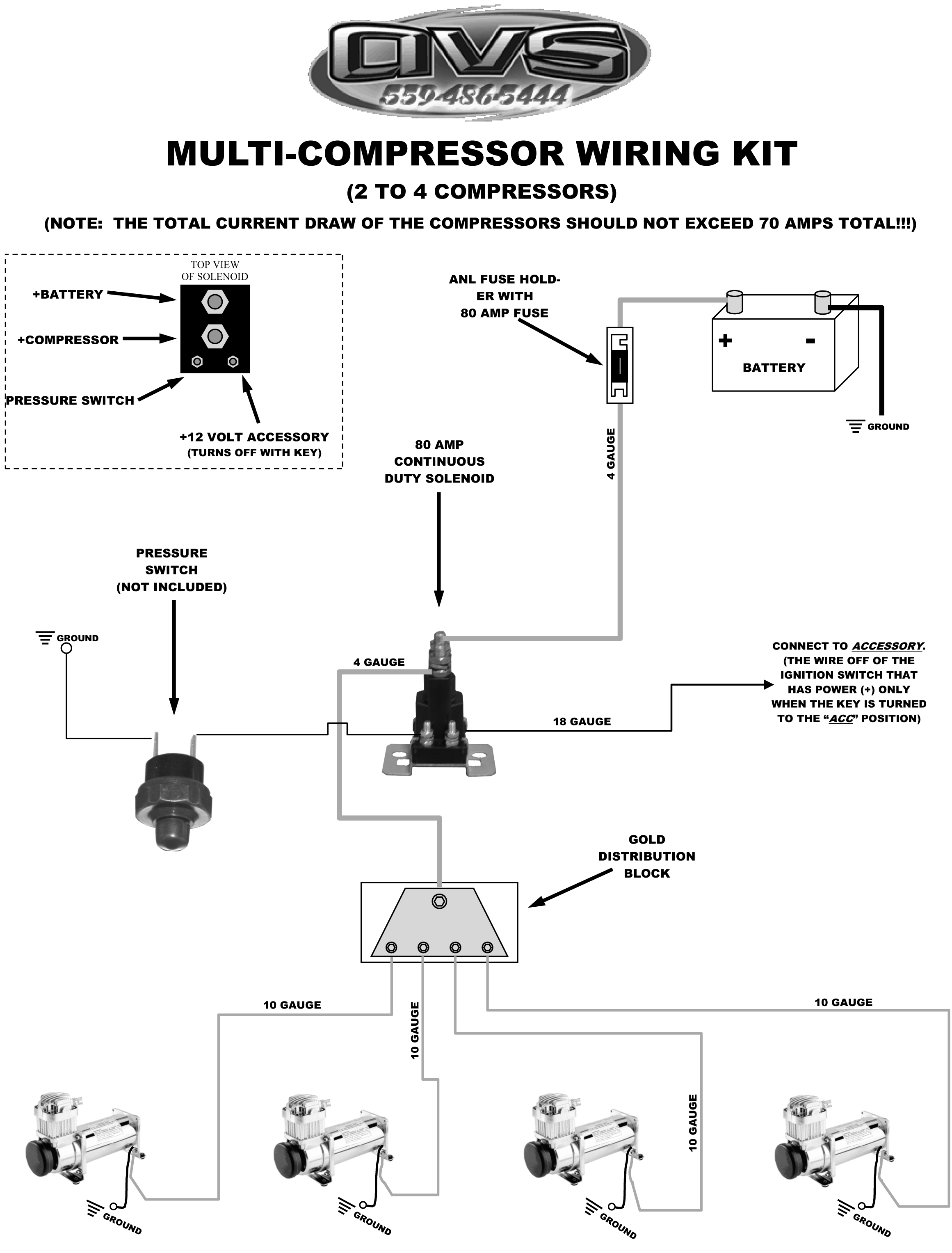
MULTI-COMPRESSOR WIRING KIT - AVS

Dual Compressor Wiring Diagram - BUSANABASEYYA
