Dimmer Switch Wiring Diagram L1 L2

Vt Commodore Ignition Wiring Diagram, Complete Wiring Diagrams For Holden Commodore VT, VX, VY, VZ, VE, VF, 5.36 MB, 03:54, 32,796, John Amahle, 2018-08-01T19:37:41.000000Z, 19, Vt Commodore Ignition Wiring Diagram, to-ja-to-ty-to-my-to-nasz-swiat.blogspot.com, 1272 x 1800, jpeg, bcm pcm 12j swiat nasz, 20, vt-commodore-ignition-wiring-diagram, Anime Arts
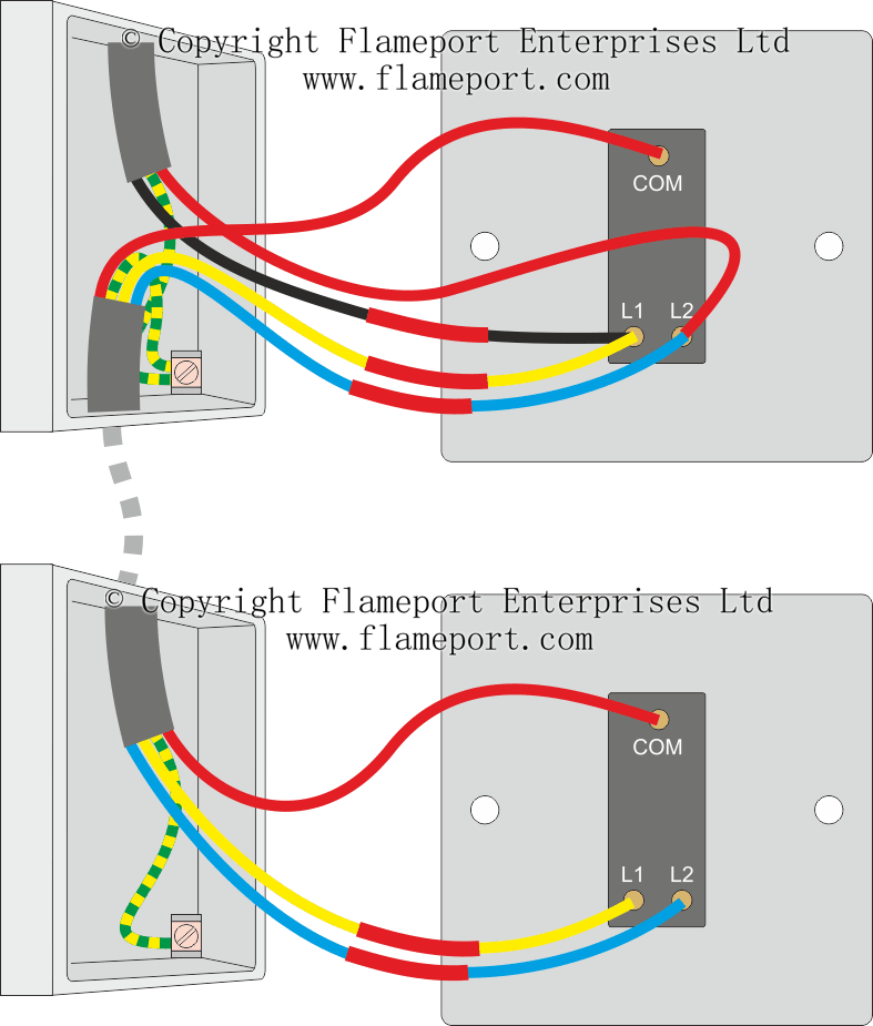
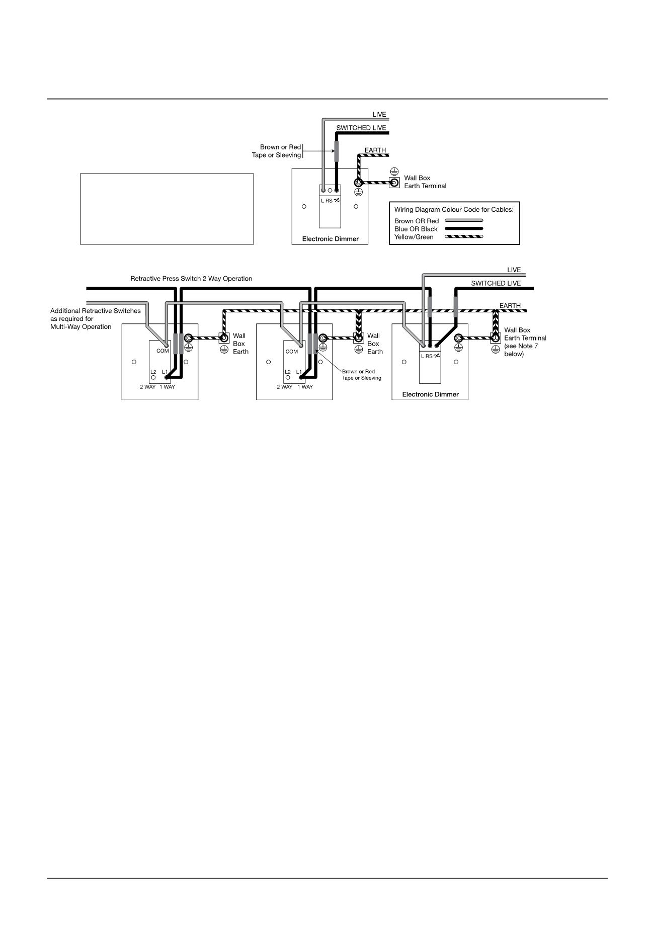
Diode clutch switch light switch light. L2 l1 com com l2 l1 l2 l1 com brown sleeve to be added to switched live for multiple gang dimmer (2, 3 & 4) repeat wiring method for each dimmer. The jumper caps can only be unplugged or plugged when the line voltage is not applied to the dimmer switch.
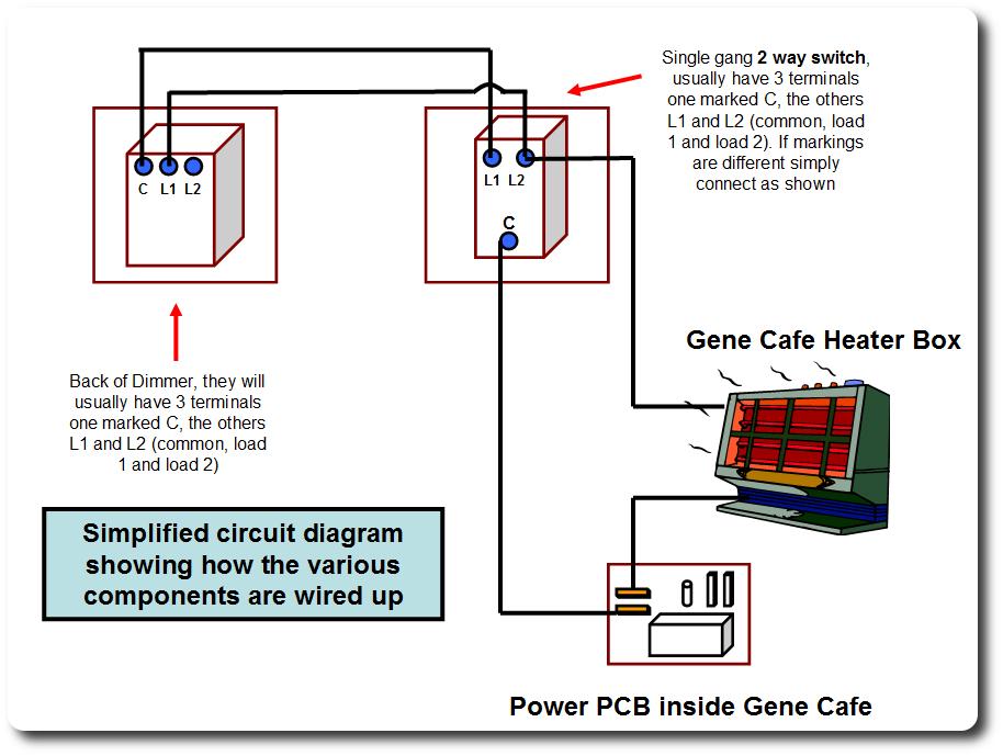
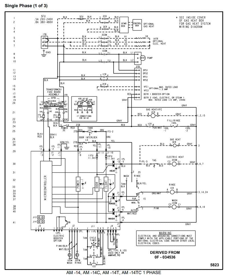
The wires fitted into the other two terminals of the old switch should be fitted either way round into terminals “l1” and “l2” of the dimmer switch. It is the screw terminal not marked l1 or l2 that is the live. The mains earth should be attached to the back box and a short length of earth wire attached from the back box to the dimmer, that way if the dimmer is removed from the wall it is still earthed and the metal back box remains earthed. F37bbc dimmer switch wiring diagram l1 l2 epanel digital books. 3 way wiring diagram uk intermediate switch l1 l2 l3 l4. Us 14 49 30 off 220v touch sensor led dimmer light switch dimmable wall touch dimmer glass panel module remote eu uk standard led lamp switch in. Assuming this switch is approved for use in canada/usa to be used in a 120 volt 15 amp single phase branch circuit i would guess that it is a double throw single pole switch. Instead of having on/off positions, it will have two on positions. Dimmer switch wiring diagram l1 l2 from www. lightwiring. co. uk.
Dimmer Switch Wiring Diagram L1 L2

Dimmer Switch Wiring Diagram L1 L2 - Database - Wiring Diagram Sample

Dimmer Switch Wiring Diagram L1 L2 - diagram types

Dimmer Switch Wiring Diagram L1 L2 - Database - Wiring Diagram Sample

Dimmer Switch Wiring Diagram L1 L2 - Database - Wiring Diagram Sample

Light Switch Wiring L1 L2 Common

Dimmer Switch Wiring Diagram L1 L2 - Database - Wiring Diagram Sample

Dimmer Switch Wiring Diagram L1 L2 - BIEYHANNY7DRAGON

[DIAGRAM] Dimmer Switch Wiring Diagram L1 L2
![Dimmer Switch Wiring Diagram L1 L2 [DIAGRAM] Dimmer Switch Wiring Diagram L1 L2](https://i.pinimg.com/originals/8a/49/03/8a4903fecdeaa6241496f7f748e6389c.png)
[DIAGRAM] Dimmer Switch Wiring Diagram L1 L2
![Dimmer Switch Wiring Diagram L1 L2 [DIAGRAM] Dimmer Switch Wiring Diagram L1 L2](https://i.pinimg.com/originals/e7/e6/46/e7e646b71388d7722b87f43c1ca91d0d.jpg)