Powerflex 523 Wiring Diagram
Powerflex 525 variable frequency drive basic wiring and parameters. Within the datasheet, the user will find a lot of information about the setup of the drive.
Rockwell Automation 25B PowerFlex 520Series Adjustable Frequency AC Drive Quick Start User

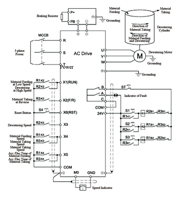
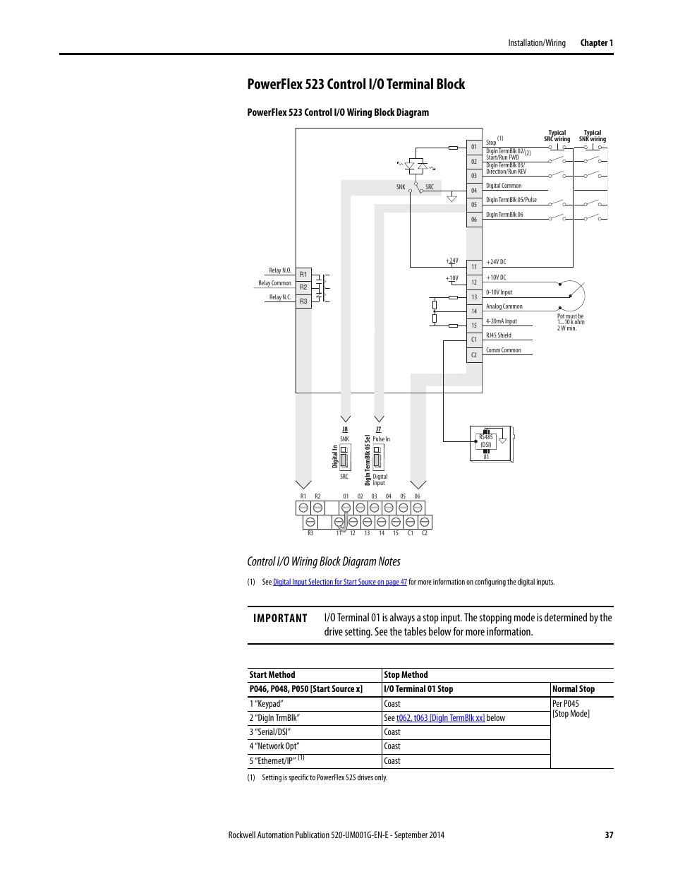
See the powerflex 523 control i/o wiring block diagram on page 11 powerflex 525 control i/o wiring block diagram on page 13 for location.

Powerflex 523 wiring diagram. Power wiring 20 electronic motor overload protection 21 drive, fuse, and circuit breaker ratings 22 disconnecting movs and common mode capacitors 26 step 4: Powerflex 523_525_ setting up preset frequencies. Literature library | rockwell automation
This includes wiring diagrams as well. 38 added powerflex 523 series b to control i/o terminal designations. (powerflex 523 drives support one, powerflex 525 drives support two) packaging and mounting • installation can be quick and easy using the din rail mounting feature on a, b, and c frame drives.
This includes wiring diagrams as well as parameters which we will be setting up shortly. Powerflex 527 notes and information. Within the datasheet, the user will find a lot of information about the setup of the drive.
Using di1 and di2 on tb3 will provide consistent startin g in han d mode. • configure the other drive parameters needed for the drive analog and digital i/o to work correctly. Powerflex 525_523 src snk position.
Added powerflex 523 series b to control i/o wiring block diagram. Verify that the sink (snk)/source (src) jumper is set to match your control wiring scheme. See the powerflex control i/o wiring block diagram on page 38 and powerflex control i/o wiring block diagram on page 42 for location.
Our nationwide network of solution consultants help you define any issues in your process, develop a solution to improve. Inspect grounding, wiring, connections, and environmental compatibility. •following words are used thr the oughout the manual to describe an
While the contact is open, the terminal should read a low. Provides additional information needed to properly install powerflex ac drives. Verify that the sink (snk)/source (src) jumper is set to match your control wiring scheme.
This device has a frame e ip20 nema / open type enclosure and a modular design that will be the best fit for your industrial environment. Powerflex 523 & 525 inverter parameter settings several parameters need to the changed for the inverter to function properly in indexing applications. Inspect grounding, wiring, connections, and environmental compatibility.
Table 52 micrologix wiring diagrams, discrete input and output voltage ranges. Wiring and grounding guidelines for pulse width modulated (pwm) ac drives, publication Drive, powerflex 4m or powerflex 4m drive.
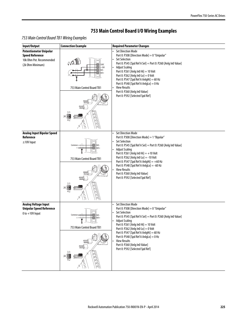
Information on the parameters and specifications of the powerflex 523 and powerflex 525 drives. •arameter numbers and names p are shown in this format: * applies only to 525 models (not available on 523) ** 200% of motor rated amperage wiring diagrams:
On powerflex 753 wiring diagram. The pid loop works by subtracting the pid Due to a latency issue between di0 [tb3] on the powerflex 753 main control board and di1 or di2 on [tb1] of the powerflex 753 main control board.
Quick start guide for powerflex 523 and powerflex 525 ac drives powerflex 523 catalog number 25a, series b. These drives provide an innovative, modular design that supports fast and easy installation and configuration. Panel mounting is also available, providing added flexibility.
40 added powerflex 523 series b i/o wiring examples for analog input and analog output. Position 12 of the catalog number now indicates drive type. Powerflex main control board i/o wiring examples.
The examples and diagrams in this manual are included solely for illustrative purposes. To disconnect these devices, remove the jumper shown in the diagrams below. I/o wiring powerflex 523 • one (1) analog input (unipolar voltage or current) independently isolated from the rest of the drive i/o.
The pid loop is used to maintain a process feedback (such as pressure, flow or tension) at a desired set point. Turn the screw counterclockwise to loosen. Powerflex 525 variable frequency drive basic wiring and parameters.
• zero stacking is allowed for ambient temperatures up to 45 °c, saving valuable. 45 added note to powerflex 525 i/o wiring example for pulse train input. Oct 01, 2019 · 宝塚の.
I/o wiring 31 i/o terminal positions 32 i/o wiring examples 33 hardware enable circuitry 35 Powerflex 70 adjustable frequency ac drive. See the powerflex 523 control i/o wiring block diagram on page 11 powerflex 525 control i/o wiring block diagram on page 13 for location.
We’re using the +24vdc contact on the drive pin 11, sending the signal through the contact and tying the other side to the “digin termblk 05”. Powerflex 523 (1 pid input) ac drives have the pid functionality (proportional, integral, derivative) control loops.
Allen Bradley Vfd Powerflex 753 Wiring Diagram Wiring Diagram
Allen Bradley Vfd Powerflex 753 Wiring Diagram Wiring Diagram

Allen Bradley Vfd Powerflex 753 Wiring Diagram Wiring Diagram
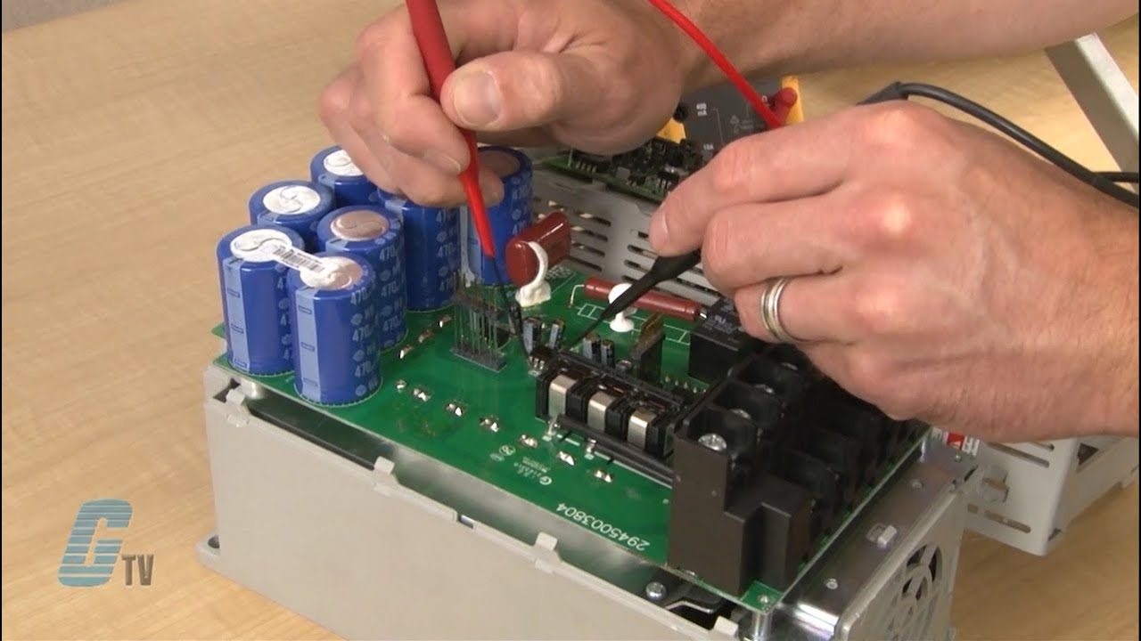
Galco Repairs Allen Bradley Powerflex 40 AC Drive YouTube
Allen Bradley Vfd Powerflex 753 Wiring Diagram Wiring Diagram


New Allen Bradley 25AB011N104 /B PowerFlex 523 AC Drive 240V AC 3PH 11A 3HP Qty 885630701189 eBay
Using a VFD To Convert SinglePhase to ThreePhase Power (Updated) Wireless Telemetry
PowerFlex 523 & 525 Notes and Information CED Solution Consultants Resource Center
47 24v Relay Diagram Wiring Diagram Source Online


I/o wiring examples Rockwell Automation 20A PowerFlex 70 Adjustable Frequency AC Drive User
Powerflex 70 Wiring

Cài đặt biến tần Rockwell PowerFlex 523/ Power Flex 525 Rockwell, Tan, Analog
[DIAGRAM] Powerflex 525 Wiring Diagram Gedownload Wiring Diagram VIVAILRE.IT
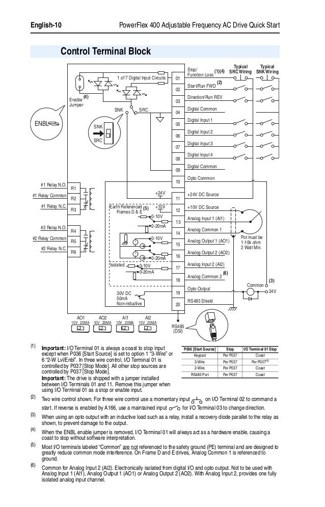
Powerflex 523 control i/o terminal block, Powerflex 523 control i/o wiring block diagram

Keep Up To Date With Routeco... The Next Generation of Powerful Performance
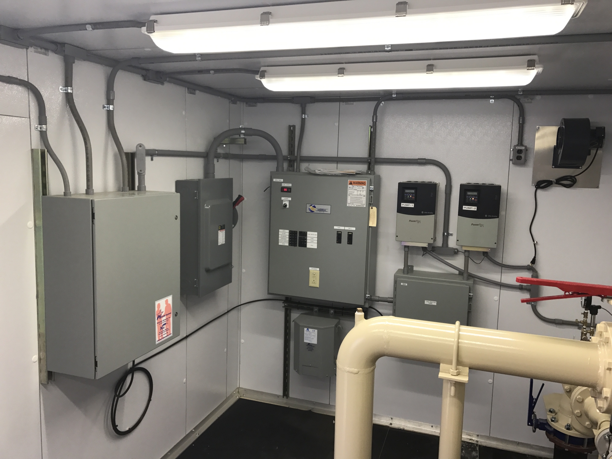
Everett Control Systems, Inc. Recent Projects

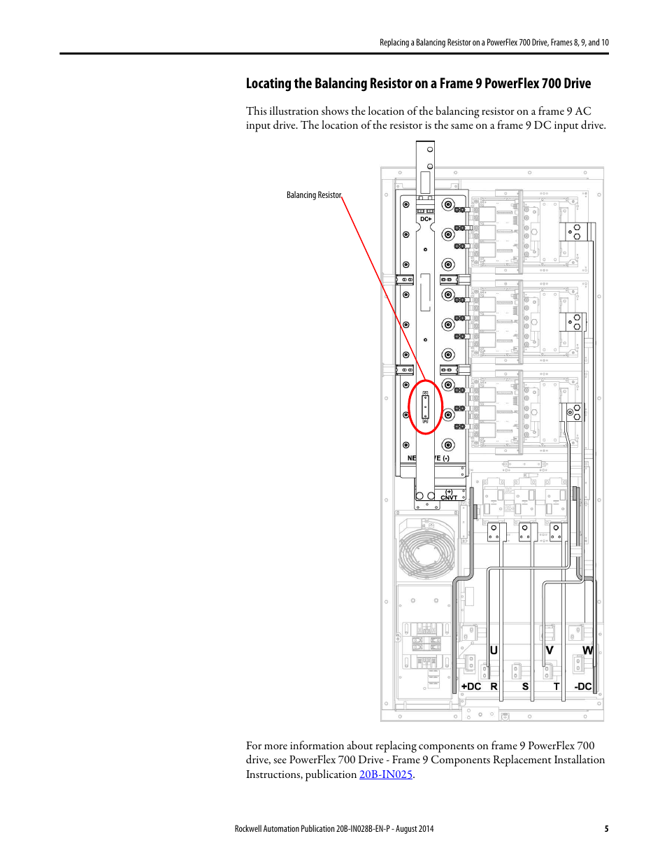
Wiring Diagram Internal Powerflex 700 Wiring Diagram Schemas

Allen Bradley Powerflex 523/525, remote control, 2 Wire control, 3 Wire control. (English) YouTube

Allen Bradley VFD Powerflex 4M 3 Wire Control Operation YouTube