12v Mosfet Amplifier Circuit Diagram
The pcb layout of this circuit diagram is below. This is the complete circuit diagram of a 1250va/24v mosfet inverter with battery charger.
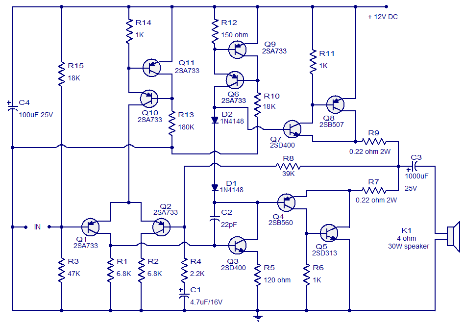
Class AB amplifier circuit operating from 12 volts, 10W
6) power up & test the circuit using a 220v led bulb.
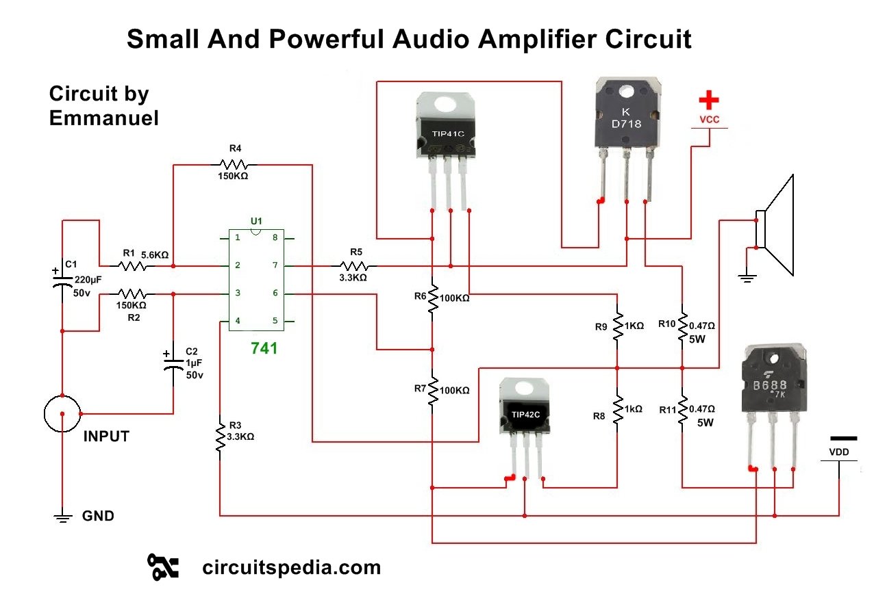
12v mosfet amplifier circuit diagram. To drive the mosfets, we power the ir2110 with 12v referenced to the negative power supply voltage; A 10k pot controls the input voltage level & a capacitor (220uf) blocks the dc component of the input signal, allowing only the ac component of the signal to move onwards. 200w, bass guitar super bridge;
C6 and c7 must be rated 50v; This is important because we are going to power the circuit with a 13.5v dc adapter, and to power the ne555 and ir2110 ic, 5v and 12v power supply is needed. Assemble the circuit on a good quality pcb.
Use 30v dc for powering the circuit. The circuit shown below is the best i tried and has enabled me to hear italian amateur signals on the 136khz band with a 1m diameter tuned loop. All used in a car or in a house with a 12v dc power supply.
Class d audio amplifier multisim live. The simple mosfet amplifier circuit diagram is super simple to build and yet will provide you with a crystal clear 100 watts of raw music power that all the listeners will cherish for a long time. Determine the dc operating point (in vns) of mosfet m determine the values of capacitors c1, c2, and c3 so that the low frequency cutoff fl is 150 hz.
This circuit uses a multivibrator circuit running in astable mode to generate a free running square wave. 200 watts mosfet amplifier class g. A 12v dc to 220 v ac converter can also be designed using simple transistors.
Which it uses just 12 volts power supply only. Other electrolytic can be 10 or 15v. Heat sink is necessary for the mosfets.
Some circuit requires high current. T1 = primary 115 [220]/secondary 8 vac transformer. Download complete pcb and parts list.
A 12 volt voltage regulator. 300w to 1200w mosfet amplifier for professionals only. For l1 make 12turns of enameled copper wire on a 1cm dia:
So i would recommend the lm6172 with a maximum slew rate of 3000 v/µs or at least 500 v/µs. Audio input from a device such as a pc or a smartphone is taken as an input to the circuit. A robust 170w class d audio power amplifier schematic diagram with lm4651 and lm4652.
Most use an ic chip. 50w bcl car audio using tda1562; The high side mosfet needs to be driven by a gate voltage that is.
This voltage is generated using a bd241 in conjunction with a 12v zener. 5) solder the output of the inverter circuit with a step up ct transformer. 50 watts mosfet amplifier circuit diagram.
The mosfet amplifier inverts the voltage signal and provides a maximal absolute gain given by the ratio r d /r s. Main operating conditions can be studied through the following image: Here the schematic diagram of 800 watt audio power amplifier with mosfet for final amplification.
200 watts mosfet amplifier class g; Smps circuit design as with atx power supplies only an etd49 core with different power traces is used. The working of this audio amplifier circuit using c5200 is as following.
How to build a high efficiency class d power amplifier circuit amp projects simple using an interesting design tl494 500w ic 555 12v car audio 50w mp7705 2x5w stereo sinewave inverter dc diagram 30 watts tda1514 40 watt under a2b module for sharc multisim live single chip 25 mono uhf searching circuits hiletgo pam8610. 12v car audio amplifier circuits. The idea was developed a long time ago by the hitachi researchers and still it remains one of the favorite designs of all time considering the.
C2 th va 100 v 10 c1 0 a. But provide higher watt power to 54 wrms at load speaker 4 ohms and there is distortion at 1% and watt power maximum 65 vrms at distortion 10%. We are going to make an amplifier circuit diagram using 4 transistors.
Electronics projects, rms 500w amplifier circuit audio amplifier circuits, transistor amplifier, date 2019/08/01. A 650v rated mosfet irfb9n65a was selected for this 12v 2 amp smps circuit prototype. The inverter implemented in this circuit is a square wave inverter and works with devices that do not require pure sine wave ac.
This amplifier can be used for practically any application that requires high power, low noise, distortion and excellent sound. Simple audio amplifier circuit diagram using transistor d718, ic tda 2030 make a 12v amplifier for the. Consider the amplifier shown below.
System 500w rms at 4 ohm 620w rms power gives 2ω, 4ω 500w rms, 8ω 380w rms circuit of the original scheme 8 mosfets used and 4ω 400w writes 2ω speakers in order to work 10 mosfet i used the original transistors toshiba. This is a car 12v audio amplifier circuit that has high power over than 50w using the ic tda1562q philips. It can be used to power lamps up to 35w but can be made to drive more powerful loads by adding more mosfets.
Circuit diagram for 12v to 220v inverter circuit working explanation. About mosfet amplifier diagram 5200 circuit.
12v 400w Audio Amplifier Circuit Diagram nerv
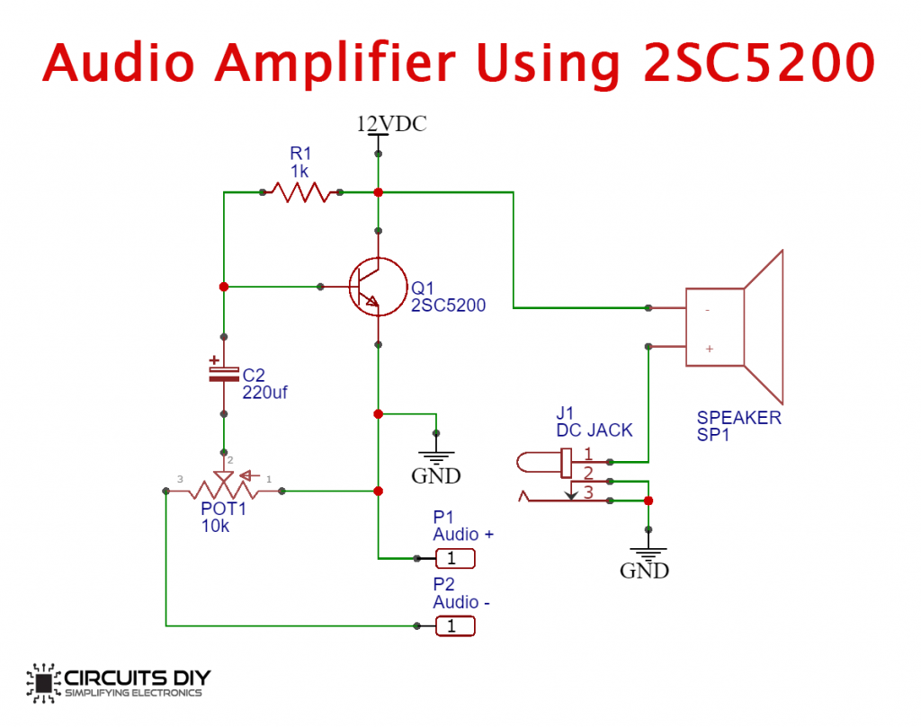
Powerful Audio Amplifier Circuit Using 2SC5200 Transistor
Car 12v Mosfet Amplifier Circuit Diagram nerv

12 Volt 2n3055 Transistor Amplifier Circuit Diagram

200W MOSFET Power Amplifier Electronic Circuit

Mosfet Circuito Amplificador De Audio 100w 12v
Diagram 3055 Transistor Audio Amplifier Circuit 12v

Stereo Audio Amplifier Using Two D718 Transistors

12 Volt 2n3055 Transistor Amplifier Circuit Diagram
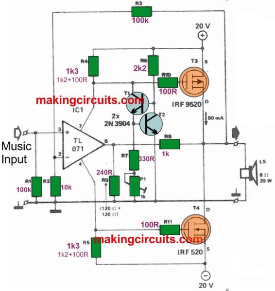
Designing a MOSFET Power Amplifier Circuit
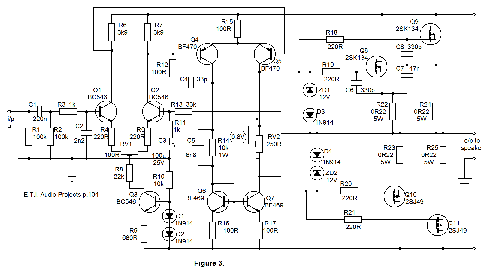
12v Mosfet Amplifier Circuit Diagram Wiring View and
12v Mosfet Amplifier Circuit Circuit Diagram Images
Circuit Diagram Of Audio Amplifier Of 12v Pdf DIAGRAM

Car 12v Mosfet Amplifier Circuit Diagram Circuit Diagram
12v Mosfet Amplifier Circuit Circuit Diagram Images
Transistor 12v Car Amp Diagrams Circuit Diagram Images


